
If you decide to do some cuttings utilizing a lasercutting machine you need the following:
- 2D CAD System that allows you to create DXF Drawings (DXF is a fileformat)
- Access to the Design in a digital way – PDF or DXF are perfect for the job
- Patience to get familiar with the tools
- Access to a lasercutting machine – can be a vendor/service company, you school/university or a FabLab (search for one close to you).
Usually Kayakers are not grown up with 2D or 3D CAD Systems like Engineers did… So get your self a copy of any open source 2D CAD System that allows to import PDF or DXF Files and write DXF Files. I would try one of the following: https://qcad.org/ or https://librecad.org/ but I work with good old AutoCAD from Autodesk and I have access to legal license… .
For a lasercutting machine it is important that you only have single lines on top of each other and you might have the possibility to engrave or cut by using different colors.
So from Björn Thomasson I’ve got the following Drawings as PDF and coverted them to DXF using AutoCAD:
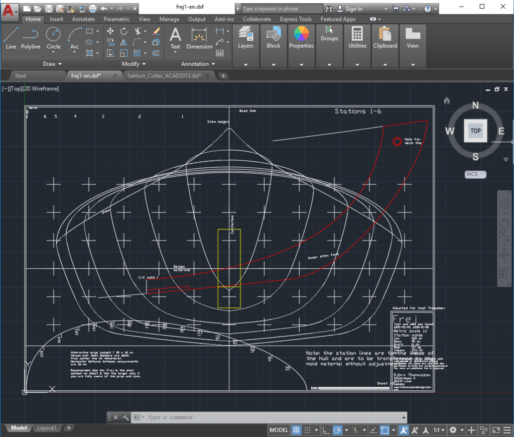
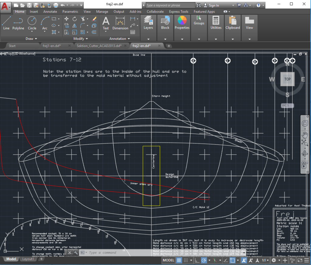
You see a lot of lines in the drawings and after saveing a backup copy of this I placed the yellow box with the dimensions of my strongback aloy profile into the drawing. You see that it is placed in a way, that only the first and last section are not punched correctly.
Make sure you copy and place the square in both halfs of the boat at the same hight. I placed it in the front half first and copied it using the centerline/waterline section as a reference point to the reare half of the boat.
The yellow box is also 1/10th of a Millimeter bigger in all dimensions than the drawings of my strongback profile. This will allow me to place the sections onto the strongback without any issue…
Next Step is to define all nessesary information – I draw a 20mm line at the intersection of deck and hull on each side. This way I have a reference line where the split happens. Also the Waterline and Centerline are essential as well as the numbering of the sections.
Than I draw the maximum dimensions of the raw material the lasercutter can work with. Afterwards I copy and place the sections together with the 20mm lines and the yellow box into the plate sketch. Goal is to place as much as possible geometry onto the raw material.
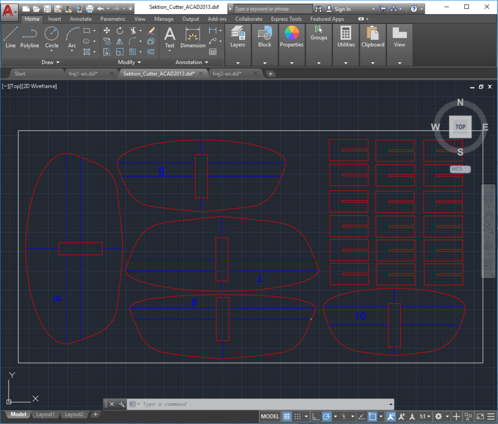
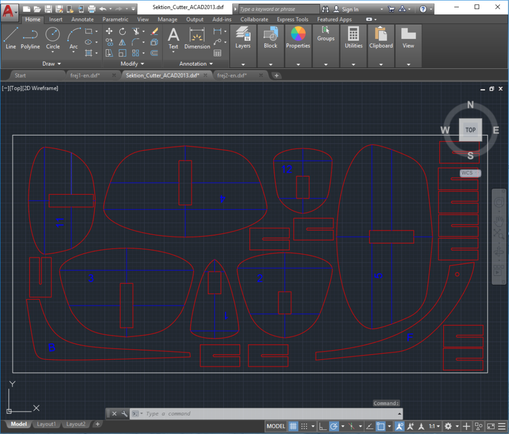
For my lasercutting vendor red means “cut” and blue means “engrave”. So after placeing the geometry onto the raw material I trimmed the lines with the sections dimension, lable everything and change colors according “cut” or “engrave”. Last but not least I filled up all empty spaces with U-Shape geometry – my “holder design” for stapleless building. We will see them later.
This raw material drawing was send to my lasercutting company. After a few days I’ve got the wood back.
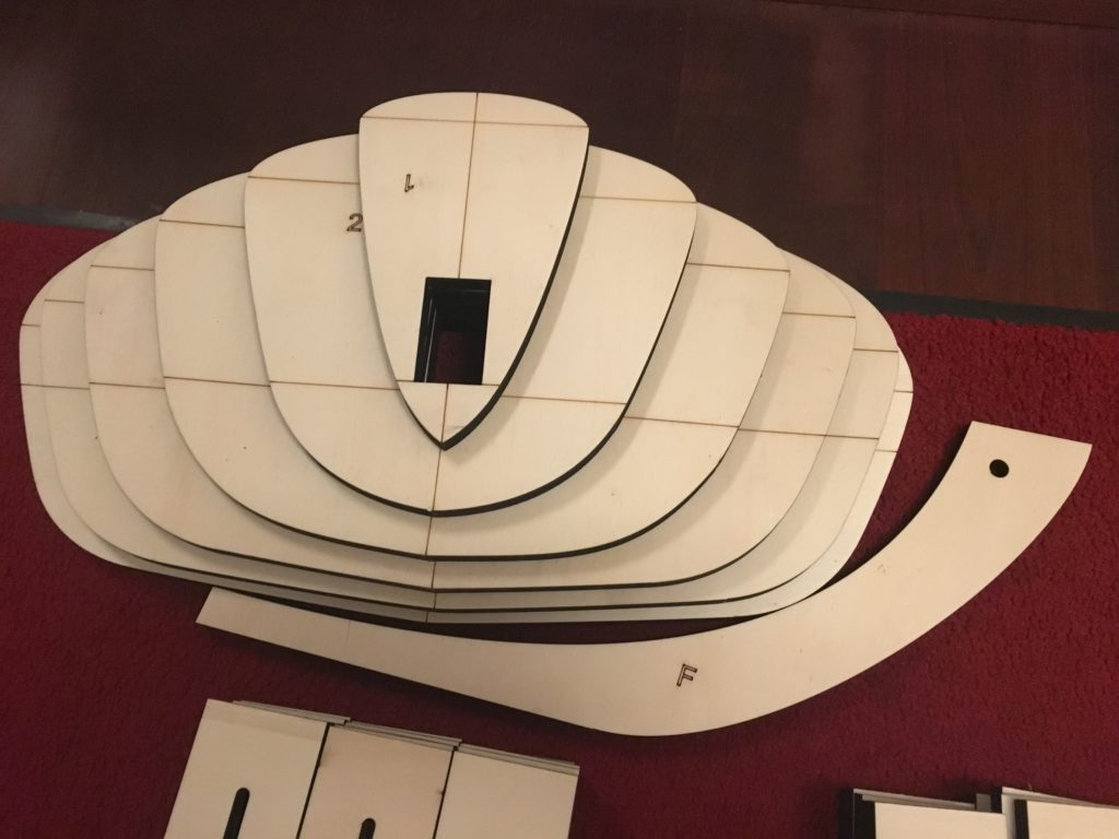
You see the engraved centerline, the intersection that devides deck and hull and the engraved numbering/lettering.
Best Regards,
Axel
One Response
Hallo Axel,
könntest Du mir bitte Deinen zuliefernden Laserbetrieb nennen?
Ich plane ähnliches und würde gerne auf eine Firma zurückgreifen, bei der die Qualität des Ergebnisses bereits bekannt ist.
Viele Grüße,
Stefan Rauchenberger